Is the Garage Open?
I was getting tired of playing with the software side of home automation so I picked an item from my wish list that would let me play with some hardware. Time to control the garage door. Besides having the ability to open the door with my phone, I figured I could use the automation part of the system to notify me when the door opens and closes as well as change the color of my LED strip as a visual indicator when the door is open. The notification light idea came about as a way to achieve a higher WAF since my wife will frequently go check to make sure the garage door didn’t get left open.
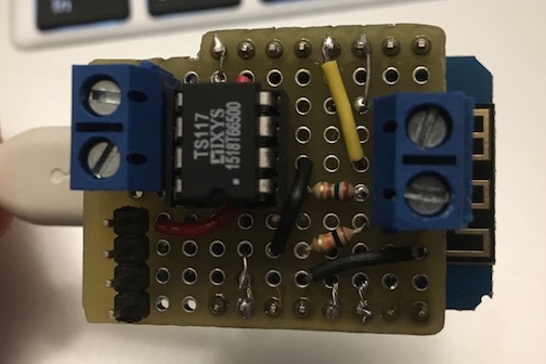
For this project I decided an ESP8266 board would be a simple way to provide the connectivity and GPIO that I needed to monitor and control the door. I have a Adafruit HUZZAH ESP8266 breakout board still attached to my LED strip, but if I was going to start installing sensors and simple controls around the house I needed a cheaper option. After looking around I decided to give the Wemos D1 mini a try because of the mini USB interface and the fact that I could get 5 for less than $30 on eBay. I didn’t buy the proto-shields that were available but I did decide that it would be the form factor for my control circuit for this project. So I cut a piece of protoboard down to size and with a little planning, was able to make it all fit using parts I had in my workshop.
For sensing the state of the garage door I used a normally closed magnetic reed switch. One side of the switch goes to ground and one side goes to an IO pin. I also connected a 10k pull up resistor to the IO pin so the pin would go high when the switch was opened. I briefly debated where to put the switch but since I want to know that the door is closed versus any other state (open, partially open, missing, etc.), I ran a wire and mounted the switch on the side of the door frame.
For the control side of the board most of the people in the forums went with an electromechanical relay but most relays are controlled with 5 volts and are huge! Well, huge when compared to the limited 10×11 hole space I had on my shield. Instead I used a opto-isolator with MOSFET output (aka solid-state relay) that I had in my drawer of chips. After a few test runs I added in a 10k pull down resistor on the IO pin because a couple of times on boot the pin floated high enough to trigger the door and the WAF would drop sharply if the door opened randomly during the next thunderstorm.
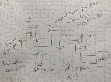
I did run into a surprise with the Wemos board when I first hooked everything up on a breadboard. I programed the chip and everything ran as expected. When I unplugged the board and plugged it back in to verify it ran on boot, the program wouldn’t run. It turns out (things you learn from reading the manual) that pins D3, D4 and D8 affect the boot mode of the Wemos. If you have these in the wrong state at boot time your program won’t start. Of course I chose D3 and D4 to be my control and sense pins and with my pull up/down resistors, I had the chip booting into programing mode. Changing IO pins was an easy fix. Move some wires, change the code and the board boots and runs every time.
I learned from my mistake with the LED control and in between designing the circuit and actually building it, I started looking to see who had some good code to run on the ESP that used MQTT for control and status. In searching the Home Assistant forums I found GarHAge. The code is well thought out, handles one or two doors, and even properly handles if the controller goes offline with MQTT Birth and LWT settings. All of the config items like wifi info, which pins you are using, and MQTT server info, is all broken out into a separate config file which made getting the code ready a really easy task. Once my circuit was ready I configured the needed variables and loaded the code on my Wemos.
On the Home assistant side of this project a garage door is considered a “cover”. The control for a cover device type provides an up, down and stop button. It also changes the active button along with the icon based on the state. Since my garage door is physically controlled by a single button this is a bit over the top but it works. This was my first cover device and I created a folder called cover and added this line to my configuration file.
cover: !include_dir_list covers/I probably won’t have any other cover devices so it might be a bit of over kill but I like having separate files for each device. So in the covers folder I created garage.yaml with the following config
platform: mqtt
name: "Garage Door"
state_topic: "garage/door/1/status"
command_topic: "garage/door/1/action"
availability_topic: "GarHAge/availability"
qos: 0
optimistic: false
retain: false
payload_open: "OPEN"
payload_close: "CLOSE"
payload_stop: "STATE"
state_open: "open"
state_closed: "closed"
payload_available: "online"
payload_not_available: "offline"
I also figured out with way to much effort that you can tell Home Assistant what type of cover you have. I don’t know if it changed the behavior of the controls but setting device_class to garage does get you an appropriate icon. So into customize.yaml went these two lines.
cover.garage_door:
  device_class: garage
I am not a fan of testing DIY electronics on expensive things like my garage door opener so once I the device was talking to Home Assistant I made sure everything worked as expected with a piece of wire, a multimeter and monitoring the serial output from the Wemos. Everything worked as expected and I was pretty sure I wasn’t going to blow anything up so I connected it to the garage door and it worked!
Getting to this point in the project I am usually temped to forget to add the finishing touches. So to remind myself I have compiled a to do list.
- Make an enclosure and properly mount my controller (currently everything is hanging from the wires).
- Add a temp sensor (hardware and software) – I did wire up an I2C header on the protoboard.
- Add an automation to notify me when the state of the garage door changes.
- Add an automation to change the color of a light if the door is left open.
- Design a PCB to replace my protoboard. As a benefit I should be able to make it support two doors.
Since I didn’t impact the normal operation of the garage door I didn’t lose any ground on the WAF. I now have three devices I can talk to and control but I still don’t have an automation. I should raise the priority on the notification light so can bump the WAF score up a few points as well as hit my original goal.
Jacob